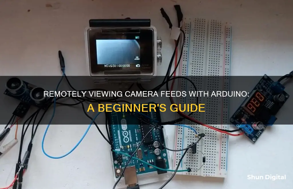
There are several ways to remotely view through a camera with an Arduino. One method involves using an Arduino board with a compatible camera unit, such as the ArduCAM and ESP8266 for remote video surveillance. Another approach is to build a custom intervalometer, which can control the shutter release of a DSLR camera at specific intervals, allowing for time-lapse photography. Additionally, Arduino can be used to create an automatic home surveillance system by connecting it to a wireless camera and controlling it through a TV. Furthermore, by combining Arduino with SensorMonkey, jQuery, and Justin.tv, it is possible to create a remote-controlled webcam with pan and tilt functionality. These examples demonstrate the versatility of Arduino in remote camera applications.
| Characteristics | Values |
|---|---|
| Camera | Lumix GH5, DSLR, ArduCAM, USB Webcam |
| Arduino | Uno, Nano, Duemilanove |
| Other Hardware | Servo Motors, Mounting Brackets, Breadboard, 3D Printer, PC, MicroSD Card, Batteries, Resistors, Transistors, Opto-isolators, IR Remote, RF434 Transmitter and Receiver, LDR Module, Relay Module, Status LED, Buzzer, Wireless Camera, TV |
| Software | Arduino Development Environment, SensorMonkey, Bloom, SensorMonkeySerialNet, jQuery UI, Justin.tv, Processing.js, IFTTT |
What You'll Learn

Using an Arduino to remotely control a webcam
The following guide will take you through the process of setting up a remote-controlled webcam using an Arduino board and other components. This project allows you to pan and tilt the webcam and stream the video feed online, which can be accessed and controlled from any device with a compatible web browser.
Components Required
- Arduino board (Uno or older versions like Duemilanove)
- USB cable to connect Arduino to a computer
- 2 x servo motors (one each for pan and tilt movements)
- Mounting brackets for the servo motors
- A base to stabilize the assembly (e.g., a mini vice)
- Webcam (ensure compatibility with your operating system)
- External power supply for the servo motors (rechargeable Ni-MH 9V batteries recommended)
- 9V to barrel jack adapter to power the Arduino
- Assorted wires for connections
- Breadboard
- Host computer with an internet connection
- Free accounts on SensorMonkey.com and Justin.tv
- Bloom software (for Windows) or SensorMonkeySerialNet (for non-Windows)
- JQuery UI library
Assembly and Setup
- Mount the Webcam and Connect the Arduino: Attach the servo motors to the mounting brackets as per the manufacturer's instructions. Secure the webcam to the top of the tilt servo's mounting bracket. Stabilize the assembly by placing it on a flat surface or attaching it to a base. Wire the servo motors to the Arduino as shown in the circuit diagram, with the tilt servo connected to analog pin 0 and the pan servo to analog pin 5.
- Power and Upload Sketch to Arduino: Connect the Arduino to a host computer using the USB cable. Power the Arduino using the external power supply through the barrel jack adapter. Upload the provided sketch to the Arduino's microcontroller using the Arduino development environment software. This sketch will control the servo motors based on incoming data.
- Install Bloom or SensorMonkeySerialNet: Install either Bloom (for Windows) or SensorMonkeySerialNet (for non-Windows) to map the serial port of the Arduino to a TCP/IP socket. This step is necessary to connect the Arduino to SensorMonkey, allowing it to communicate over the network.
- Login to SensorMonkey and Publish Stream: Sign in to SensorMonkey using your Facebook account and create a personal namespace. In the 'Control' tab, test the pan and tilt assembly by sending commands to the Arduino. Navigate to the 'Stream' tab and publish the stream as 'Private' to allow remote clients to send data to the Arduino.
- Login to Justin.tv and Publish Video Stream: Create an account on Justin.tv and start broadcasting your live webcam feed. This service will provide the live audio/video streaming for your webcam.
- Create a Webpage to Remotely Control the Webcam: Download the jQuery UI library and place it in the same directory as your webpage. Edit the provided HTML code to include your SensorMonkey namespace, private key, and Justin.tv channel name. Upload this code to a public web server to access and control your webcam feed from any compatible device.
By following these steps, you can set up a remote-controlled webcam system using an Arduino and various software tools. This project allows for the remote control of the webcam's pan and tilt movements, as well as live streaming of the video feed, which can be accessed and manipulated from any web-enabled device.
Restore Camera DVR Footage After Power Outage
You may want to see also

How to remotely trigger a camera with an Arduino
Capturing the perfect photo can be challenging, but with the help of an Arduino, you can remotely trigger your camera to capture that perfect moment with precision. Here's a step-by-step guide on how to remotely trigger a camera using an Arduino:
Step 1: Understanding the Basics
Most cameras have the option to use an external shutter remote. By creating a simple computer system, you can trigger the shutter at the exact moment you want to take a picture. For this project, you will need an Arduino board, a camera with remote control capabilities, and some basic electronic components.
Step 2: Choosing the Right Camera
Select a camera that has a remote control input, which can be used to focus and trigger the camera shutter. In the example provided, a Lumix GH5 camera is used. However, you can choose a different camera model that suits your specific needs and requirements.
Step 3: Building the Circuit
The circuit for this project is relatively simple. You will need to place a resistor of approximately 2.2 kOhms between the innermost poles on the 2.2 mm jack of your camera. When you don't want to trigger the shutter, the same poles should see a resistance of (36 kOhms + 2.9 kOhms + 2.2 kOhms) = 41.1 kOhms. This "idle" resistance allows the camera to sense that an external remote is connected. You can use a breadboard to create this setup, and a 40 kOhm resistor worked well for the "idle" resistance in the provided example.
Step 4: Controlling the Shutter
To control the shutter release, you can use an optocoupler or a relay. In the example provided, an optocoupler was chosen due to its proximity. The "trigger circuit" is controlled by a regular output on the Arduino. Additionally, an LG-JG20MA sensor was connected to the Arduino to trigger it. The specific firmware code is provided in the source material and can be referenced for your project.
Step 5: Putting It All Together
Now, it's time to test your setup. In the provided example, a small yellow box was pushed down from a table, triggering the sensor as it fell towards a box filled with water. The Arduino then counted down a delay, after which it triggered the shutter on the camera using its output and the "trigger circuit". The shutter was successfully triggered at the perfect time, demonstrating the effectiveness of the system.
Step 6: Advanced Techniques
While the basic setup is functional, you can explore more advanced techniques for improved results. In the example provided, the images taken in a dark cave without much external light were rather ugly due to high ISO noise. You can experiment with different lighting conditions, shutter speeds, and ISO settings to enhance the quality of your images. Additionally, you can explore other sensors and advanced camera models to further refine your remote triggering system.
Exploring Global Camera Feeds: A Step-by-Step Guide
You may want to see also

Building a home surveillance system with an Arduino
In this guide, we will be building a simple and cheap automatic home surveillance system using an Arduino. The goal of this project is to achieve a surveillance system that operates without any manual interference. Unlike other surveillance systems, this setup will not require you to manually power on the TV and camera receiver every time, nor will it need any user input to view who is outside your door.
Components Required:
- Arduino Uno board: The Arduino Uno will act as the brain of our project, controlling other modules in the receiver section.
- IR remote control unit: This will be used to control the TV using the Arduino.
- RF434 receiver module: This module will receive data from the RF434 transmitter module in the transmitter section.
- Wireless camera receiver: This module will receive the wireless camera signal from the transmitter section.
- Relay module: Used to turn the power of the wireless camera receiver on or off.
- Status LED: Indicates whether the surveillance mode is on or off. A red LED will glow when the door is closed, and a blue LED will glow when the door is opened.
- Buzzer: Produces a sound when someone presses the calling button outside.
- Transmitter section: This includes a battery or power supply adapter, RF434 transmitter module, wireless camera, and door sensors.
Setting Up the Receiver Section:
Connect the IR remote control unit, RF434 receiver module, wireless camera receiver, relay module, status LED, and buzzer to the Arduino as per the circuit diagram. The wireless camera receiver output will be connected to the AV3 port of your TV using an AV cable.
Setting Up the Transmitter Section:
The transmitter section does not require a microcontroller. Connect the battery or power supply adapter to the RF434 transmitter module and the wireless camera. The door sensors are just two wires that indicate whether the door is open or closed.
Programming the Arduino:
You will need to program the Arduino to control the TV and camera receiver automatically. First, you will need to read the remote button codes using the IRremote library file of Arduino. Then, you can upload the main program code provided in the sources. Make sure to put your TV remote button hex codes in the corresponding positions in the code.
Testing the System:
Once you have set up the receiver and transmitter sections and programmed the Arduino, it's time to test your automatic home surveillance system. When someone presses the calling bell outside your door, the signal will be sent to the receiver section using wireless data transmission. The receiver section will then turn on the TV and change the input source to the wireless camera receiver. You can then see who is at the door and decide whether to open it. When the door is opened, the transmitter will sense it and send a signal to the receiver, which will change the TV source back to the previous input.
By following the steps outlined above, you can create a simple and inexpensive automatic home surveillance system using an Arduino. This system will allow you to monitor your home remotely and conveniently, providing an extra layer of security and peace of mind.
Sunlight Photography: Capturing the Perfect Shot
You may want to see also

Using an Arduino to remotely control a DSLR camera
DSLR cameras offer a range of features that allow skilled photographers to capture incredible photos and videos. While modern smartphone cameras can also take and save high-quality images, they don't offer the same level of control over factors such as aperture, shutter speed, and ISO settings. Additionally, DSLRs are compatible with various accessories, including intervalometers, which can be used to create stunning time-lapse videos.
To remotely control a DSLR camera using an Arduino, you can create a simple computer system that triggers the camera shutter at the perfect moment. This can be achieved by using the remote control input on the camera, which allows for focus and shutter control. By connecting an Arduino to this input, you can program it to trigger the shutter at specific intervals or in response to certain stimuli.
One example of an Arduino-controlled DSLR camera project is the Arduino Nano intervalometer. This project uses an Arduino Nano, a 4-position DIP switch, a 50 to 200-ohm resistor, a double coin cell (or other 6V) battery pack, and a 2.5 mm wired stereo plug. The Arduino Nano is connected to the camera's intervalometer interface, which typically consists of a 2.5 mm stereo jack with sections corresponding to ground, auto-focus, and shutter release.
To build this project, you will need to create a circuit that includes the Arduino Nano and the other components mentioned above. The circuit can be laid out on a breadboard, but for a more durable and portable solution, you can design a 3D-printed base to hold the intervalometer. The Arduino Nano is then programmed with specific code to control the timing of the shutter release.
Another example of an Arduino-controlled DSLR camera project is a multi-functional DSLR remote control. This project uses an Arduino Pro Mini, various resistors, an LCD display, an IR LED, and other components. The remote control replicates the IR command pulse that the DSLR responds to, allowing for features such as intervalometer, light detection, motion sensing, and manual control. The mode of operation can be selected using a switch, and the settings can be adjusted using potentiometers.
By using an Arduino to remotely control a DSLR camera, photographers can unlock a range of creative possibilities and capture unique images and videos that would not be possible with a smartphone camera or a basic DSLR setup. These projects showcase the versatility of Arduino and its ability to enhance the capabilities of existing technology.
Remotely Viewing Kamtron Cameras: A Step-by-Step Guide
You may want to see also

How to remotely control a camera shutter with an Arduino
Capturing the perfect moment in time with a camera can be challenging. While most cameras have the option to use an external shutter remote, connecting a regular button may not yield the desired results. However, with an Arduino, you can create a simple computer system to capture that perfect moment. Here is a step-by-step guide on how to remotely control a camera shutter with an Arduino:
Step 1: Understanding the Camera
Most cameras have the capability to use an external shutter remote. For this project, we will be using a Lumix GH5 camera, which has a remote control input that can be utilised for focusing and triggering the camera shutter.
Step 2: Triggering the Shutter
To trigger the shutter remotely, a resistor of approximately 2.2 k Ohms needs to be placed between the innermost poles on the 2.2 mm jack. When the shutter is not being triggered, the same poles need to see a resistance of approximately 41.1 k Ohms (36 k Ohms + 2.9 k Ohms + 2.2 k Ohms). This "idle" resistance likely serves the purpose of allowing the camera to detect the presence of an external remote.
Step 3: Breadboard Setup
For this project, a breadboard setup can be used. A 40 k Ohm resistor can be utilised for the "idle" resistance, and a 2.2 k Ohm resistor can be placed in parallel when triggering the shutter. The insertion of the 2.2 k Ohm resistor can be controlled by an optocoupler or a similar component, such as a relay.
Step 4: Arduino Connection
The "trigger circuit" is controlled by a regular output on the Arduino. Additionally, an LG-JG20MA sensor is connected to the Arduino. This sensor is responsible for triggering the Arduino to capture the image.
Step 5: Firmware
The following firmware can be utilised for this project:
#define SENSOR_PIN 3
#define TRIGGER_PIN 2
Void setup() {
PinMode(TRIGGER_PIN, OUTPUT);
DigitalWrite(TRIGGER_PIN, LOW);
PinMode(SENSOR_PIN, INPUT_PULLUP);
Serial.begin(9600);
}
Void camera_trigger(){
DigitalWrite(TRIGGER_PIN, HIGH);
Delay(100);
DigitalWrite(TRIGGER_PIN, LOW);
}
Uint8_t read_sensor(){
Return digitalRead(SENSOR_PIN);
}
Void loop() {
If(!read_sensor()){
Delay(270);
// Delay after triggering the sensor
Camera_trigger();
Delay(2000);
// Random "back off" delay
}
}```
Step 6: Putting It All Together
Now, it's time to assemble the components and test the setup. This can be done by setting up a demonstration, such as
By following these steps, you can successfully remotely control a camera shutter with an Arduino, allowing you to capture images at precise moments with ease.
Caught on Camera: Where to Watch This Show
You may want to see also
Frequently asked questions
You can use an external shutter remote to control a camera shutter with an Arduino. You can use an LG-JG20MA sensor connected to an Arduino to trigger the shutter at the perfect moment.
You can use an Arduino Nano intervalometer to control a DSLR camera. You will need an Arduino Nano, a 4-position DIP switch, a 50 to 200-ohm resistor, a double coin cell (or other 6V) battery pack, and a 2.5 mm wired stereo plug. You can follow the wiring diagram and code provided in the source material.
You can set up an automatic home surveillance system using an Arduino Uno board, an IR remote control unit, an RF434 receiver module, and a wireless camera receiver. The Arduino can be programmed to control the TV and camera receiver, and the system can be triggered by a calling bell or door sensor.
You can set up video streaming and face recognition using an ESP32-CAM board, female-to-female jumper wires, and the Arduino IDE. You will need to install the ESP32 add-on and use the CameraWebServer example code. You will also need to insert your network credentials and select the correct camera module.


