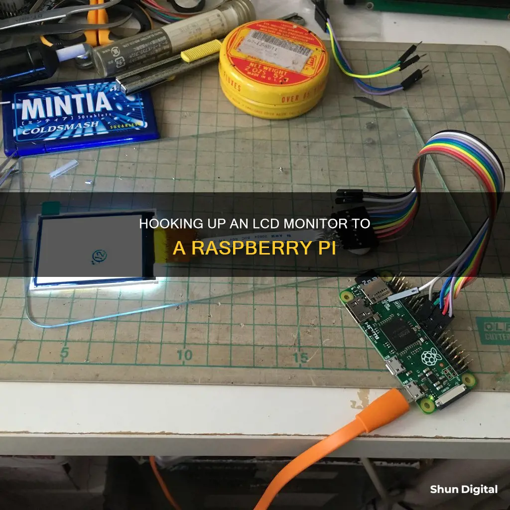
There are a variety of ways to connect an LCD monitor to a Raspberry Pi, with the most common being HDMI. However, if you want to directly connect an LCD monitor to a Raspberry Pi, you can use the GPIO pins. This is a simple process, as the LCD module comes with Raspberry Pi's GPIO pin-compatible female headers. This means that you just have to plug in your display module to your Raspberry Pi's GPIO pins.
If you are using a Raspberry Pi Touch Display, you can connect it to the Raspberry Pi using the DSI connector.
| Characteristics | Values |
|---|---|
| Display Type | LCD Touchscreen |
| Display Size | 3.2-inch |
| Resolution | 320x240 |
| Connection Type | SPI |
| Connection Port | GPIO |
What You'll Learn

Connect the LCD to the Raspberry Pi using the GPIO pins
To connect an LCD to a Raspberry Pi using the GPIO pins, you will need to follow these steps:
- Purchase a compatible LCD screen -- You will need to purchase an LCD screen that is compatible with the Raspberry Pi. Some recommended screens include the Waveshare SpotPear 3.2-inch LCD display, the SainSmart 3.2-inch LCD touchscreen, and the Eleduino 3.5-inch LCD.
- Connect the LCD to the Raspberry Pi -- Once you have purchased a compatible LCD screen, you can connect it to the Raspberry Pi by plugging it into the GPIO pins. The LCD screen should have a female header that is compatible with the Raspberry Pi's GPIO pins. Make sure that the connections are secure before proceeding.
- Install the necessary drivers -- In order for the LCD screen to function properly, you will need to install the appropriate drivers. This can be done by following the instructions provided by the manufacturer of the LCD screen or by using a general-purpose driver such as the FBTFT driver.
- Configure the display settings -- After installing the drivers, you may need to configure the display settings to ensure that the LCD screen is recognized by the Raspberry Pi. This can include editing configuration files such as /boot/config.txt and /boot/cmdline.txt, as well as enabling the SPI interface in the raspi-config menu.
- Test the LCD screen -- Once the drivers and display settings have been configured, you can test the LCD screen by rebooting the Raspberry Pi and verifying that the display is functioning properly. If the LCD screen is not working as expected, you may need to troubleshoot the connection and configuration settings.
Monitor Measurements: Understanding Screen Sizes for Optimal Viewing
You may want to see also

Set up the Raspberry Pi to display onto the LCD
The setup process will vary depending on the type of LCD display and the Raspberry Pi model you are using.
Raspberry Pi Touch Display
If you are using the official Raspberry Pi Touch Display, you can connect it to the Raspberry Pi using the DSI connector. This display is compatible with all models of Raspberry Pi except the Raspberry Pi Zero and Zero 2 W, which lack a DSI connector.
Using an LCD Touchscreen
If you are using an LCD touchscreen, you will need to interface the LCD display with your Raspberry Pi. This typically involves installing various drivers and making changes to the kernel.
- Enable SPI Communication: By default, SPI communication is disabled. If you are using a version of Raspbian released after January 31, 2015, you can enable SPI in the raspi-config menu. For earlier versions, you will need to remove the entry from the blacklist file by commenting out the line that says "blacklist spi-bcm2708" in the raspi-blacklist.conf file.
- Configure the fbturbo Driver: You need to configure the fbturbo video driver to output the Raspberry Pi's display to the SPI bus instead of the HDMI bus. Open the 99-fbturbo.conf file and change the line "Option "fbdev" "/dev/fb0"" to "Option "fbdev" "/dev/fb1".
- Install the fbtft Drivers: Download and install the drivers and kernel modules required to run the LCD touchscreen. You can use the following command:
Sudo REPO_URI=https://github.com/notro/rpi-firmware rpi-update
Configure the Kernel Modules: Edit the /etc/modules file to configure the kernel modules for the LCD display and touchscreen sensors. Add the following code below the snd-bcm2835 line to support the fbtft_device and ads7846_device modules:
> spi-bcm2708 fbtft_device name=waveshare32b gpios=dc:22,reset:27 speed=48000000 waveshare32b width=320 height=240 buswidth=8 init=-1,0xCB,0x39,0x2C,0x00,0x34,0x02,-1,0xCF,0x00,0XC1,0X30,-1,0xE8,0x85,0x00,0x78,-1,0xEA,0x00,0x00,-1,0xED,0x64,0x03,0X12,0X81,-1,0xF7,0x20,-1,0xC0,0x23,-1,0xC1,0x10,-1,0xC5,0x3e,0x28,-1,0xC7,0x86,-1,0×36,0x28,-1,0x3A,0x55,-1,0xB1,0x00,0x18,-1,0xB6,0x08,0x82,0x27,-1,0xF2,0x00,-1,0×26,0x01,-1,0xE0,0x0F,0x31,0x2B,0x0C,0x0E,0x08,0x4E,0xF1,0x37,0x07,0x10,0x03,0x0E,0x09,0x00,-1,0XE1,0x00,0x0E,0x14,0x03,0x11,0x07,0x31,0xC1,0x48,0x08,0x0F,0x0C,0x31,0x36,0x0F,-1,0×11,-2,120,-1,0×29,-1,0x2c,-3 ads7846_device model=7846 cs=1 gpio_pendown=17 speed=1000000 keep_vref_on=1 swap_xy=0 pressure_max=255 x_plate_ohms=60 x_min=200 x_max=3900 y_min=200 y_max=3900
Edit the /boot/cmdline.txt File: Replace the code in this file with the following code, entered in one single line:
Dwc_otg.lpm_enable=0 console=ttyAMA0,115200 console=tty1 root=/dev/mmcblk0p2 rootfstype=ext4 elevator=deadline rootwait fbtft_device.custom fbtft_device.name=waveshare32b fbtft_device.gpios=dc:22,reset:27 fbtft_device.bgr=1 fbtft_device.speed=48000000 fbcon=map:10 fbcon=font:ProFont6x11 logo.nologo dma.dmachans=0x7f35 console=tty1 consoleblank=0 fbtft_device.fps=50 fbtft_device.rotate=0
- Configure startx to Load Automatically: If you want the Pi to load startx automatically and boot to the GUI, add the line "su -l pi -c startx" above the line that says "exit 0" in the /etc/rc.local file.
- Set the System to Boot to the Desktop GUI: If you are using the Raspberry Pi 2 Model B, set the system to boot to the desktop GUI in the raspi-config menu.
- Reboot the Raspberry Pi: After completing all the steps, reboot the Raspberry Pi. The GUI should appear on the LCD screen.
Note: Some LCD touchscreens may come with an OS image file that you can write to your SD card for a quick setup. However, if you want to run a clean, updated version of Raspbian or a different OS, you will need to configure the touchscreen from scratch.
Additionally, if you are using a Raspberry Pi Zero, you can add a GPIO pin array to the board. This can be done by soldering or using solderless, hammer-in pin headers. The Raspberry Pi Zero also has a TV-out feature, which allows you to connect to a TV or monitor using an RCA cable or jack.
Removing Splendid Demo from Your ASUS Monitor
You may want to see also

Install and configure the FBTFT drivers
To install and configure the FBTFT drivers, you will need to follow several steps. Firstly, you will need to clone the bb-kernel repo and checkout the am33x-v3.8 branch using the following command:
$ git clone https://github.com/RobertCNelson/bb-kernel
$ git checkout am33x-v3.8
Next, move into the new branch directory and run the build kernel script:
Make -j4 ARCH=arm LOCALVERSION=-bone79 CROSS_COMPILE=”ccache /home/afustini/dev/bbb/bb-kernel/dl/gcc-linaro-arm-linux-gnueabihf-4.7-2013.04-20130415_linux/bin/arm-linux-gnueabihf-” dtbs
Once the build script has been executed, you can proceed to add the FBTFT drivers into the Linux kernel source. Follow the instructions provided in the fbtft README file. Navigate to the bb-kernel dir and use the following commands:
$ cd KERNEL/drivers/video
$ git clone https://github.com/notro/fbtft
After the FBTFT drivers have been added, verify that the files have been modified correctly by using the diff command and checking the output. Make the necessary changes to the KERNEL/drivers/video/Kconfig and KERNEL/drivers/video/Makefile files as outlined in the FBTFT README file.
Now, rebuild the kernel using the rebuild script:
$ ./tools/rebuild.sh
Follow the screenshots provided in the guide to select the FBTFT drivers in the kernel configuration menu. After exiting the menu, the rebuild script will continue the process.
Verify that the fbtft modules have been compiled successfully by using the find command and checking the output. Also, verify that the kernel and tarballs have been created by checking the bb-kernel/deploy directory.
The next step is to install the new kernel on an SD card. Use the install_kernel.sh script provided in the bb-kernel directory. Make sure to edit the script to specify the correct device for your SD card. Run the script with sudo privileges to install the new kernel onto the microSD card.
Finally, boot your BeagleBone Black with the updated microSD card. You should see the new kernel version displayed during bootup. Verify that the FBTFT drivers are loaded by checking the /lib/modules/ directory.
For Raspberry Pi users, the process may vary depending on the specific model and hardware configuration. Some Raspberry Pi displays connect via the DSI connector, while others use the GPIO pins. In some cases, you may need to install device drivers and make changes to the kernel configuration. Refer to the official Raspberry Pi documentation and community forums for specific instructions related to your hardware setup.
Host Resource Monitor: Tracking Guest Memory Usage?
You may want to see also

Download and install the drivers and kernel modules
Downloading and installing the drivers and kernel modules is a crucial step in setting up an LCD touchscreen on the Raspberry Pi. Here's a detailed guide on how to do it:
Step 1: Enable SPI Communication
By default, SPI communication is disabled on the Raspberry Pi. To enable it, you need to make changes in the raspi-config menu or by editing the blacklist file, depending on your Raspbian version.
For Raspbian versions released after January 31, 2015, open the raspi-config menu and enable SPI.
For older Raspbian versions, use the following command to edit the blacklist file and remove the spi-bcm2708 driver:
Sudo nano /etc/modprobe.d/raspi-blacklist.conf
Comment out the line that says "blacklist spi-bcm2708" by adding a "#" at the beginning of the line. Save and exit the file.
Step 2: Configure the fbturbo Video Driver
The fbturbo video driver needs to be configured to output the Raspberry Pi's display to the SPI bus instead of the HDMI bus. Use the following command to edit the configuration file:
Sudo nano /usr/share/X11/xorg.conf.d/99-fbturbo.conf
Find the line that says "Option "fbdev" "/dev/fb0"" and change "fb0" to "fb1". This tells the video driver to output the display to the LCD screen instead of HDMI.
Step 3: Install the fbtft Drivers
Download and install the required drivers and kernel modules to run the LCD touchscreen. Use the following command:
Sudo REPO_URI=https://github.com/notro/rpi-firmware rpi-update
This will download the necessary files. After the download is complete, reboot the Raspberry Pi with the command "sudo reboot".
Step 4: Configure the Kernel Modules
Edit the "/etc/modules" file to configure the kernel modules for the LCD display and touchscreen sensors. Use the following command:
Sudo nano /etc/modules
Add the following code below the "snd-bcm2835" line to support the "fbtft_device" and "ads7846_device" modules:
Spi-bcm2708 fbtft_device name=waveshare32b gpios=dc:22,reset:27 speed=48000000 waveshare32b width=320 height=240 buswidth=8 init=-1,0xCB,0x39,0x2C,0x00,0x34,0x02,-1,0xCF,0x00,0XC1,0X30,-1,0xE8,0x85,0x00,0x78,-1,0xEA,0x00,0x00,-1,0xED,0x64,0x03,0X12,0X81,-1,0xF7,0x20,-1,0xC0,0x23,-1,0xC1,0x10,-1,0xC5,0x3e,0x28,-1,0xC7,0x86,-1,0×36,0x28,-1,0x3A,0x55,-1,0xB1,0x00,0x18,-1,0xB6,0x08,0x82,0x27,-1,0xF2,0x00,-1,0×26,0x01,-1,0xE0,0x0F,0x31,0x2B,0x0C,0x0E,0x08,0x4E,0xF1,0x37,0x07,0x10,0x03,0x0E,0x09,0x00,-1,0XE1,0x00,0x0E,0x14,0x03,0x11,0x07,0x31,0xC1,0x48,0x08,0x0F,0x0C,0x31,0x36,0x0F,-1,0×11,-2,120,-1,0×29,-1,0x2c,-3 ads7846_device model=7846 cs=1 gpio_pendown=17 speed=1000000 keep_vref_on=1 swap_xy=0 pressure_max=255 x_plate_ohms=60 x_min=200 x_max=3900 y_min=200 y_max=3900
Make sure to replace "waveshare32b" with the appropriate device name if you are using a different LCD screen.
Step 5: Edit the /boot/cmdline.txt File
Edit the "/boot/cmdline.txt" file, which contains the settings used to configure the system during boot. Use the following command:
Sudo nano /boot/cmdline.txt
Replace the code in this file with the following, ensuring that it is entered as a single line:
Dwc_otg.lpm_enable=0 console=ttyAMA0,115200 console=tty1 root=/dev/mmcblk0p2 rootfstype=ext4 elevator=deadline rootwait fbtft_device.custom fbtft_device.name=waveshare32b fbtft_device.gpios=dc:22,reset:27 fbtft_device.bgr=1 fbtft_device.speed=48000000 fbcon=map:10 fbcon=font:ProFont6x11 logo.nologo dma.dmachans=0x7f35 console=tty1 consoleblank=0 fbtft_device.fps=50 fbtft_device.rotate=0
Again, replace "waveshare32b" with the appropriate device name if necessary.
Step 6: Configure startx to Load Automatically
The final step is to set up the Raspberry Pi to load startx automatically and boot to the GUI. If you prefer to boot to the command prompt, skip this step. Use the following command:
Sudo nano /etc/rc.local
Add the line "su -l pi -c startx" above the line that says "exit 0". Save and exit the file.
For the Raspberry Pi 2 Model B, set the system to boot to the desktop GUI in the raspi-config menu.
After completing these steps, your Raspberry Pi should be successfully configured to work with the LCD touchscreen.
How VMware's Hardware Usage Monitor Optimizes Performance
You may want to see also

Configure the kernel modules for the LCD display and touchscreen sensors
After the Pi is booted up and you’ve logged back in, the next step is to configure the kernel modules for the LCD display and touchscreen sensors. To do that, we need to edit the /etc/modules file. So enter this at the command prompt:
`sudo nano /etc/modules
The first term of each line in this file is the name of a kernel module that will be loaded automatically at boot time. The terms after the name of the kernel module on each line are called parameters, and parameters can be changed to adjust the properties of each kernel module.
Currently, the only module that is set to load automatically is snd-bcm2835, which is the module for the Raspberry Pi’s Broadcom processor.
Add this code below the snd-bcm2835 line to support the fbtft_device and ads7846_device modules:
`fbtft_device name=waveshare32b gpios=dc:22,reset:27 speed=48000000
`waveshare32b width=320 height=240 buswidth=8 init=-1,0xCB,0x39,0x2C,0x00,0x34,0x02,-1,0xCF,0x00,0XC1,0X30,-1,0xE8,0x85,0x00,0x78,-1,0xEA,0x00,0x00,-1,0xED,0x64,0x03,0X12,0X81,-1,0xF7,0x20,-1,0xC0,0x23,-1,0xC1,0x10,-1,0xC5,0x3e,0x28,-1,0xC7,0x86,-1,0x36,0x28,-1,0x3A,0x55,-1,0xB1,0x00,0x18,-1,0xB6,0x08,0x82,0x27,-1,0xF2,0x00,-1,0x26,0x01,-1,0xE0,0x0F,0x31,0x2B,0x0C,0x0E,0x08,0x4E,0xF1,0x37,0x07,0x10,0x03,0x0E,0x09,0x00,-1,0XE1,0x00,0x0E,0x14,0x03,0x11,0x07,0x31,0xC1,0x48,0x08,0x0F,0x0C,0x31,0x36,0x0F,-1,0x11,-2,120,-1,0x29,-1,0x2c,-3`
`ads7846_device model=7846 cs=1 gpio_pendown=17 speed=1000000 keep_vref_on=1 swap_xy=0 pressure_max=255 x_plate_ohms=60 x_min=200 x_max=3900 y_min=200 y_max=3900
Note: Line 5 is long so make sure you get everything, and use cut/paste to avoid typos. The file should look something like this now:
The kernel module for the LCD screen is called fbtft_device and the kernel module for the touchscreen is called ads7846_device. ads7846 is the name of the touchscreen controller chip used in the Waveshare 3.2″ LCD and many other touchscreen displays.
If you are not using the Waveshare 3.2″ Touchscreen LCD, first find the fbtft_device name of your device by checking here. Next, on the line that begins with fbtft_device, change the term name=waveshare32b to name=YOUR DEVICE NAME. Now, on the next line that begins with waveshare32b, change the waveshare32b term to your own device name, for example adafruit28, or sainsmart32_spi.
Removing OSD from Your ASUS ROG Monitor
You may want to see also
Frequently asked questions
An LCD display is a Liquid Crystal Display that can be used to show the output of your Raspberry Pi. A touchscreen display is an LCD display with a touch-sensitive interface that allows you to interact with the Raspberry Pi by touching the screen.
There are several ways to connect an LCD display to your Raspberry Pi. The most common way is to use a High-Definition Multimedia Interface (HDMI) cable. Other ways include using a Display Serial Interface (DSI) cable, a General Purpose Input/Output (GPIO) pin array, or a composite video out port.
Yes, you can use an LCD display with a Raspberry Pi Zero. However, the Raspberry Pi Zero does not have an HDMI connector, so you will need to use an adapter, such as a mini HDMI adapter.
Yes, you can use a touchscreen display with a Raspberry Pi. Touchscreen displays are available for all models of Raspberry Pi, except for the Raspberry Pi Zero and Zero 2 W, which lack a DSI connector.
To enable the LCD display on your Raspberry Pi, you will need to edit the configuration files. This can be done using a text editor such as Nano. The specific steps will depend on the type of LCD display and the version of the Raspberry Pi operating system you are using.


