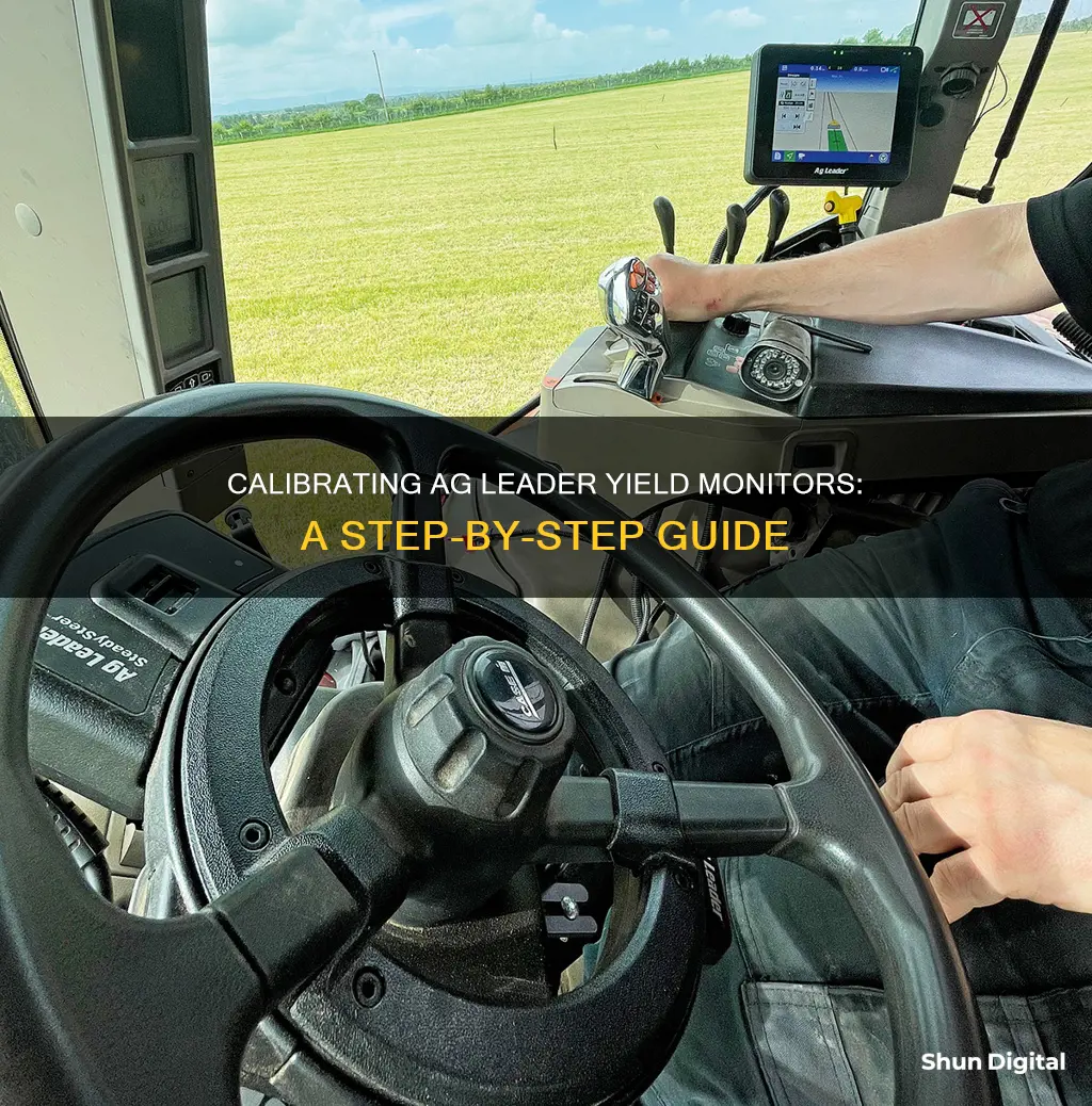
Calibrating an Ag Leader yield monitor is a crucial step in ensuring accurate yield data, which is essential for making informed decisions about crop management and profitability. Improper calibration can lead to erroneous data that is challenging to interpret. To calibrate the Ag Leader yield monitor effectively, it is important to familiarise yourself with the device and its components. This can be achieved through on-site support, training sessions, user manuals, and online resources. The specific calibration method outlined in the manufacturer's owner's manual should be followed, and it may involve multiple sensors that need to be calibrated in a particular sequence. Additionally, it is important to back up data, check cables and connections, ensure sensor cleanliness, and verify proper installation.
| Characteristics | Values |
|---|---|
| Calibration Difficulty | Confusing and time-consuming |
| Calibration Importance | Improperly calibrated yield monitors can generate erroneous data |
| Calibration Time | InCommand's simplified calibration process decreases calibration effort required |
| Calibration Loads | 4-6 calibration loads |
| Calibration Method | Refer to the manufacturer's owner operation manual |
| Calibration Tips | On-site support, training sessions, user manuals, and online information |
| Calibration Frequency | Perform periodic calibration loads throughout a lengthy harvest season |
| Calibration Accuracy | 1% error or less |
What You'll Learn

Understand the components of the Ag Leader yield monitor
Understanding the components of the Ag Leader yield monitor is essential for effective calibration and optimal performance. Here is a detailed breakdown of its key components:
Power System: The Ag Leader yield monitor relies on power from the combine's batteries. It is crucial to ensure that the power system is well-maintained, with a particular focus on the alternator or generator. Clean electrical ground connections are also essential for the system's functionality.
Cable Harness: The cable harness connects various yield monitor components. It is important to inspect the wires within the harness for any wear or damage that could lead to short circuits. This includes examining the main power cable from the battery to the monitor in the cab and then back to each sensor.
Flow Sensor: The flow sensor is typically mounted at the top of the clean grain elevator. It is essential to verify its proper installation and maintain the correct paddle clearance. The distance from the paddle tip to the deflector plate in the clean grain elevator must be within the specified range for optimal performance. Additionally, keep an eye out for any rodent damage to the flow sensor wires on the load cell.
Deflectors and Impact Plate: These components channel the grain toward the sensor. It is important to check for any wear or breakage on the deflectors and ensure that the impact plate is not worn thin or broken. Referring to the installation instructions can help verify that everything is in proper alignment.
Grain Moisture/Temperature Sensor: This sensor measures the moisture and temperature of the grain. Ensure that it is clean and free of any mud or crop residue. Verify that it has a good electrical ground connection and that the fuse, switch, and relay for the motorized auger are functioning correctly.
Elevator Speed Sensor: Located on the shaft driving the clean grain elevator, this sensor monitors the elevator's speed. It is crucial to ensure that the tee cable is properly connected so that speed output is accurately transmitted to the combine gauges and the yield monitor.
Ground Speed Sensor: The ground speed sensor is typically located at the top of the transmission. It uses a tee cable to share speed output with the combine gauges and the yield monitor, contributing to the overall accuracy of the system.
Display: The display is the user interface of the Ag Leader yield monitor. It is important to ensure that it has the latest firmware upgrades and that the date is displaying correctly. The display should indicate whether all components are functioning correctly and properly connected.
Data Storage: The Ag Leader yield monitor utilizes data cards, memory cards, or USB drives to store the collected data. Ensure that the data card is functioning correctly and properly connected to the display. It is also important to back up data regularly to prevent loss or damage.
GPS Receiver: The GPS receiver provides positional information for the yield monitor. It is crucial to verify that the GPS receiver is functioning accurately and providing differential correction.
In-Cab Display: The in-cab display is where the operator interacts with the yield monitor. It provides real-time data, such as yield and moisture maps, and allows for adjustments and calibration.
Understanding these components and their functions is crucial for effective calibration and optimal performance of the Ag Leader yield monitor.
Ankle Monitor Offenses: Understanding Criminal Triggers
You may want to see also

Check the power system and cable harness
To check the power system and cable harness of your Ag Leader yield monitor, you must pay special attention to the power system on the machine with a well-maintained alternator/generator. Inspect for clean electrical ground connections all around. Ag electronics get their power from the combine batteries, so it is important to ensure these connections are in good condition.
The cable harness is responsible for connecting several yield monitor components. The wires in the harness need to be inspected for wear and damage that may cause a short circuit. Begin by checking the main power cable at the battery, moving up to the monitor in the cab, and then back to each of the sensors. Ensure that all wires are intact and free of damage.
It is also important to verify that the cable harness is securely connected to the monitor and sensors. Check for any signs of corrosion or damage on the connections. If any issues are found, the cable harness may need to be replaced.
By following these steps, you can ensure that the power system and cable harness of your Ag Leader yield monitor are in proper working condition, which is crucial for accurate and reliable performance in the field.
Enabling Monitor Mode: WiFi Card Compatibility Check
You may want to see also

Verify the flow sensor and deflectors
To verify the flow sensor and deflectors of your Ag Leader yield monitor, you must check that the flow sensor is properly installed and has the correct paddle clearance. The paddle clearance is the distance from the tip of the paddle closest to the deflector plate in the clean grain elevator. This value must be within 3/8” to 5/8” for most combine models and 1 1/2” for Lexion combines.
Also, check for rodent damage to the flow sensor wires on the load cell. Look for any worn or broken deflectors that channel the grain toward the sensor. You may want to compare the current state of the impact plate with a picture of a new one in the installation instructions to verify that everything is as it should be.
Additionally, ensure that the impact plate is not worn thin or broken. The flow sensor's impact or deflector plate should be inspected for wear, and if there is any damage, the plate should be replaced. There have been cases where holes in the plate have resulted in inaccurate yield readings.
Best Monitor Size for Call of Duty Experience
You may want to see also

Ensure the moisture/temperature sensor is clean
To ensure the moisture/temperature sensor is clean, follow these steps:
Locate the sensor: The moisture/temperature sensor is typically located on the underside of the Ag Leader yield monitor. It is usually a small, flat, disc-shaped device with a metal probe in the centre.
Turn off the device: Before cleaning the sensor, make sure the yield monitor is turned off and unplugged to avoid any accidental damage or incorrect readings.
Gently clean the sensor: Use a soft, dry cloth to carefully wipe down the surface of the sensor. Remove any visible dirt, debris, or residue that may have accumulated. Avoid using any liquids or cleaning solutions, as moisture can damage the sensor.
Be cautious of the probe: Take extra care around the metal probe in the centre of the sensor, as it is delicate and crucial for accurate readings. Do not apply pressure or use sharp objects to clean this area. A gentle wiping motion with a soft cloth should be sufficient.
Check for damage: After cleaning, inspect the sensor for any signs of damage, such as scratches, nicks, or corrosion. If any damage is observed, do not use the sensor and consult a qualified technician for advice or repair.
By following these steps, you can ensure that the moisture/temperature sensor is clean and in optimal condition, which is crucial for obtaining accurate data and extending the lifespan of your Ag Leader yield monitor. Regular maintenance and care of the sensor will ensure reliable performance and accurate yield monitoring.
Monitor Multitasking: 3-Screen Setup for Ultimate Productivity
You may want to see also

Check the elevator and ground speed sensors
To check the elevator and ground speed sensors of your Ag Leader yield monitor, you must first locate them. The elevator speed sensor is located on the end of the shaft that drives the clean grain elevator, while the ground speed sensor is located at the top of the transmission.
For the elevator speed sensor, ensure that the tee cable is properly connected so that speed output is available to both the combine gauges and the yield monitor. Check that the tee cable is not damaged or worn, as this could impact the accuracy of the sensor.
Next, check the ground speed sensor. This sensor uses a tee cable to share speed output between the combine gauges and the yield monitor. Again, ensure that the tee cable is properly connected and not damaged or worn.
It is important to verify that both sensors are functioning correctly and providing accurate speed output. This can be done by engaging the separator and observing the elevator speed on the in-cab display. Any issues with the sensors should be addressed before using the yield monitor.
In addition to checking the elevator and ground speed sensors, it is also important to inspect the other components of the yield monitor, such as the power system, cable harness, flow sensor, deflectors, impact plate, grain moisture/temperature sensor, display, and data. By thoroughly checking each of these areas, you can help ensure that your Ag Leader yield monitor is ready for the harvest season and provide accurate data for crucial decision-making.
Hooking Up Your NEC Monitor: A Step-by-Step Guide
You may want to see also
Frequently asked questions
Before operating your Ag Leader Yield Monitor, it is important to check the following:
- Display indicates everything is functioning correctly or is properly connected.
- Memory card or USB drive is installed properly, if required.
- Proper communication between the data card and the in-cab display.
- DGPS receiver is providing a position and has differential correction.
- Header switch for starting and stopping data collection is set.
- Stop-height switch operates properly when raising and lowering the header.
- Row width is set according to the number of rows for a row crop header or the appropriate width of a cutting platform header.
- Ground speed sensor is calibrated, if not using GPS.
During operation, it is important to periodically perform calibration loads to check or improve the accuracy of weight estimates. Recalibration is also required if you observe:
- More than a 5% difference in weight calibration errors.
- 5-pound per bushel differences in grain test weight.
- Temperature changes greater than 10 degrees.
After operation, it is important to:
- Remove your memory card or USB drive from the display when not in use.
- Back up data onto your computer and data storage devices frequently throughout the harvest season.


