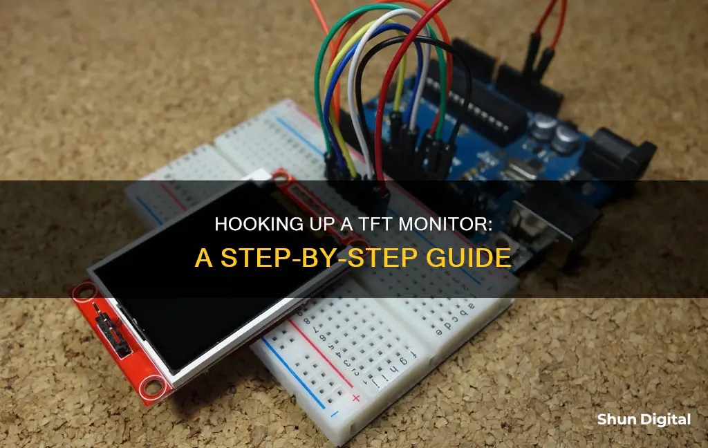
TFT monitors are a cheap and versatile way to add a visual display to your project. In this article, we will discuss how to hook up a TFT monitor to an Arduino. We will cover the necessary hardware, software, and libraries you will need to get your TFT monitor up and running. We will also provide a step-by-step guide to connecting your TFT monitor and provide troubleshooting tips if you encounter any issues. By the end of this article, you should be able to confidently hook up your TFT monitor and utilise its colourful graphic display capabilities.
| Characteristics | Values |
|---|---|
| Display resolution | 128 x 128 pixels, 128 x 160 pixels, 176x220 resolution, 320x240 resolution, 220x176 resolution |
| Pins | 8 pins, 11 pins and 5 pins, 18 pins |
| Power pins | 5V, 3.3V |
| Arduino pins | 2-9, 7, 8, 11, 10, 13, 9, 10 |
| Mega pins | 22-29 |
| Control lines | 4 or 5 |
| CS (Chip Select) | Analog 3 |
| C/D (Command/Data) | Analog 2 |
| WR (Write) | Analog 1 |
| RD (Read) | Analog 0 |
| RST (Reset) | Arduino Reset line |
What You'll Learn

How to hook up a TFT display to an Arduino
In this tutorial, you will learn how to hook up a TFT display to an Arduino. You will learn how to wire the display, write text, draw shapes, and display images on the screen.
Introducing the TFT Display
The TFT display is a colorful display with 128 x 160 color pixels. The display can load images from an SD card – it has an SD card slot at the back. The following figure shows the screen front and back view.
This module uses SPI communication – see the wiring below. To control the display, you will use the TFT library, which is already included with Arduino IDE 1.0.5 and later.
Wiring the TFT Display to Arduino
The table below shows the TFT display wiring to Arduino UNO.
| TFT Display | Arduino Uno |
|---|---|
| CS | 10 |
| DC | 9 |
| RST | 8 |
| SCK | 13 |
| MOSI | 11 |
| MISO | 12 |
| VCC | 5V |
| GND | GND |
Note: different Arduino boards have different SPI pins. If you’re using another Arduino board, check the Arduino official documentation.
Initializing the TFT Display
The TFT display communicates with the Arduino via SPI communication, so you need to include the SPI library in your code. You will also use the TFT library to write and draw on the display.
Cpp
#include
#include
Then, you need to define the CS, A0 (or DC) and RST pins:
Cpp
#define cs 10
#define dc 9
#define rst 8
Create an instance of the library called TFTscreen:
Cpp
TFT TFTscreen = TFT(cs, dc, rst);
Finally, in the setup(), you need to initialize the library:
Cpp
TFTscreen.begin();
Writing Text on the TFT Display
To write text on the display, you can customize the screen background color, font size and color.
To set the background color, use:
Cpp
TFTscreen.background(r, g, b);
In which, r, g and b are the RGB values for a given color. To choose font color:
Cpp
TFTscreen.stroke(r, g, b);
To set the font size:
Cpp
TFTscreen.setTextSize(2);
You can increase or decrease the number given as an argument to increase or decrease font size.
Finally, to draw text on the display, you use the following line:
Cpp
TFTscreen.text("Hello, World!", x, y);
In which “Hello, World!” is the text you want to display and the (x, y) coordinate is the location where you want to start displaying text on the screen.
The following example displays “Hello, World!” in the middle of the screen and changes the font color every 200 milliseconds.
Cpp
#include
#include
#define cs 10
#define dc 9
#define rst 8
TFT TFTscreen = TFT(cs, dc, rst);
Void setup() {
TFTscreen.begin();
TFTscreen.background(0, 0, 0);
}
Void loop() {
Int redRandom = random(0, 255);
Int greenRandom = random(0, 255);
Int blueRandom = random(0, 255);
TFTscreen.stroke(redRandom, greenRandom, blueRandom);
TFTscreen.text("Hello, World!", 6, 57);
Delay(200);
}
Drawing Shapes on the TFT Display
The TFT library provides useful functions to draw shapes on the display:
Cpp
TFTscreen.point(x, y)
TFTscreen.line(xStart, yStart, xEnd, yEnd)
TFTscreen.rect(xStart, yStart, width, height)
TFTscreen.circle(x, y, radius)
The following example displays several shapes. Every time the code goes through the loop, the shapes change color.
Cpp
#include
#include
#define cs 10
#define dc 9
#define rst 8
TFT TFTscreen = TFT(cs, dc, rst);
Void setup() {
TFTscreen.begin();
TFTscreen.background(0, 0, 0);
}
Void loop() {
Int redRandom = random(0, 255);
Int greenRandom = random(0, 255);
Int blueRandom = random(0, 255);
TFTscreen.stroke(redRandom, greenRandom, blueRandom);
TFTscreen.point(80, 64);
Delay(500);
TFTscreen.line(0, 64, 160, 64);
Delay(500);
TFTscreen.rect(50, 34, 60, 60);
Delay(500);
TFTscreen.circle(80, 64, 30);
Delay(500);
TFTscreen.background(0, 0, 0);
}
Displaying Images on the TFT Display
The TFT display can load images from the SD card. To read from the SD card, you use the SD library, already included in the Arduino IDE software. Follow the next steps to display an image on the display:
- Solder header pins for the SD card. There are four pins opposite to the display pins, as shown in the figure below.
- The display can load images bigger or smaller than the display size (160 x 128 px), but for better results, edit your image size to 160 x 128 px.
- The image should be in .bmp format. To do that, you can use a photo editing software and save the image as .bmp format.
- Copy the image to the SD card and insert it on the SD card slot at the back of the display.
- Wire the SD card pins to the Arduino by following the table below:
| SD Card | Arduino Uno |
|---|---|
| CS | 10 |
| MOSI | 11 |
| SCK | 13 |
| MISO | 12 |
| GND | GND |
| <
Monitoring CPU Usage: JMeter's Performance Insights
You may want to see also

How to connect pins to a breadboard
A breadboard is a rectangular plastic board with a bunch of tiny holes in it. These holes let you easily insert electronic components to prototype an electronic circuit. The connections are not permanent, so it is easy to remove a component if you make a mistake, or just start over and do a new project.
Breadboards are designed so you can push the pins of electronic components into the holes. They will be held in place snugly enough that they will not fall out (even if you turn the breadboard upside down), but lightly enough that you can easily pull on them to remove them. The inside of a breadboard is made up of rows of tiny metal clips. When you press a component's pin into a breadboard hole, one of these clips grabs onto it.
To connect pins to a breadboard, simply push the pins of the component into the holes. The pins will be held in place by the metal clips inside the breadboard. Make sure that the pins are pushed in firmly all the way, otherwise, you may end up with loose connections that lead to strange circuit behaviour.
When connecting pins to a breadboard, it is important to follow the correct circuit diagram and to be aware of the numbering and labelling of the rows and columns on the breadboard. This will help you to make the correct connections and avoid short circuits. It is also important to use the correct type of wire for your connections. Single-core plastic-coated wire of 0.6mm diameter is typically recommended, as stranded wire may crumple when pushed into the holes and damage the breadboard.
- Connect a wire from the VCC power rail to the positive, anode leg of the LED.
- Connect the negative, cathode leg of the LED to a 330Ω resistor.
- Connect the resistor to a button.
- When the button is pushed, it will connect the circuit to ground and complete the circuit, turning on the LED.
Connecting the GA-970A-DS3P EX to a Monitor: A Step-by-Step Guide
You may want to see also

How to install the Arduino libraries
To install the Arduino libraries, follow these steps:
First, you need to identify the display. This involves checking for identifying information printed on the display or matching its appearance with pictures on Google Images to determine the display's resolution and driver chip.
Next, find out if there is an Arduino driver available by searching online. Henning Karlsen's UTFT library, for example, works with many displays.
Once you've found a compatible library, download and install it. If you're using a Linux machine, copy the library archive file to the /usr/share/arduino/libraries directory and untar or unzip it.
Now, you need to figure out the hardware connections, i.e., which display pins are wired to which pins on the Arduino.
After that, load an example sketch into the Arduino IDE and upload it to the Arduino board with the wired-up TFT display.
With the display functional, you can start using it with your Arduino projects.
Additionally, you can install Arduino libraries through the Arduino IDE Library Manager. Here's how:
- In the Arduino IDE menu bar, select Tools > Manage Libraries.
- In the sidebar, click on the button to open the Library Manager.
- Filter the available libraries by typing a keyword or library name in the text field above the listed libraries.
- Find the library you want to install in the search results and click Install.
- Wait for the installation to complete.
- Click "More info" to learn more about the library, which will usually take you to a reference page or repository.
You can also import a .zip library by going to Sketch > Include Library > Add .ZIP Library in the menu bar. Then, navigate to the .zip file's location, extract it, and move the main folder to the "libraries" folder inside your sketchbook. Finally, restart the Arduino IDE.
TFT vs LCD: Understanding Monitor Technology
You may want to see also

How to solder
To connect a TFT LCD screen to a breadboard, you will need to solder a connector to the flex band. This can be done using a soldering iron with a 1mm or smaller bit. Here is a step-by-step guide on how to solder:
Step 1: Prepare your workspace
Before you begin soldering, gather all the necessary tools and materials, including a soldering iron, solder, flux, and a clean work surface. Ensure adequate ventilation in the work area to avoid inhaling fumes.
Step 2: Tin the soldering iron tip
Apply a small amount of solder to the tip of the soldering iron. This helps to transfer heat more effectively and protects the tip from corrosion.
Step 3: Heat the joint
Place the components you wish to join together, ensuring they are properly aligned. Touch the heated tip of the soldering iron to the joint, allowing the heat to flow through the pieces.
Step 4: Apply solder
With the joint heated, feed the solder into the connection, allowing it to melt and flow into the joint. Be careful not to use too much solder, as this can lead to messy joints.
Step 5: Remove the soldering iron
Once the solder has melted and filled the joint, remove the soldering iron. Allow the solder to cool and solidify, forming a strong mechanical and electrical connection.
Step 6: Inspect the joint
Use a magnifying glass or microscope to inspect the solder joint. Look for any signs of solder bridges, which can cause short circuits. If present, use a solder wick to remove the excess solder.
Step 7: Clean the flux
Use isopropyl alcohol (IPA) to clean up any excess flux residue from the board. IPA is readily available in small bottles sold as camera lens cleaning fluid.
Step 8: Tape the connection
To protect the solder joints and prevent them from flexing, apply a strip of electrical insulation tape over the connections.
Step 9: Test the connection
After allowing the solder to cool completely, test the TFT monitor connection to ensure it is functioning properly.
Note: Always follow safety precautions when soldering. Wear safety goggles to protect your eyes from hot solder and fumes, and work in a well-ventilated area to avoid inhaling harmful fumes.
Monitoring Electricity Usage: A Guide to Tracking Your Power Consumption
You may want to see also

How to identify the display
TFT stands for Thin-Film Transistor. TFT displays are a versatile technology used in a wide range of applications. These displays consist of minuscule pixels, each governed by individual transistors. This level of control ensures precision in managing colour and brightness. Liquid crystals are used to manipulate light to produce a spectrum of colours. Voltage-induced changes in the crystals' orientation regulate the amount of light passing through each pixel.
TFT displays are capable of swiftly refreshing pixels, making them ideal for delivering seamless animations and facilitating multimedia content. They also support touch interfaces and provide immediate visual feedback.
TFT displays employ two transparent glass substrates, sandwiching a liquid crystal material between them. Each pixel is composed of three sub-pixels, one each for red, green, and blue, the primary colours that combine to create a full spectrum of colours. The liquid crystal material in each sub-pixel interacts with polarised light, and the orientation of the liquid crystals determines the colour and intensity of light transmitted.
When an electric charge is applied to the thin-film transistor beneath a specific pixel, it acts as a switch, altering the orientation of the liquid crystals in that sub-pixel. This modulation of the liquid crystals allows different amounts of light to pass through, creating the desired colour for that pixel.
The TFT array, consisting of millions of these transistors, is responsible for independently controlling each pixel's colour and brightness. By selectively activating individual transistors, the display creates intricate images and videos with stunning clarity and vividness.
To achieve a full-colour display, TFTs use a technique known as "colour filtering". Each sub-pixel contains a colour filter corresponding to red, green, or blue. When light passes through the liquid crystals, the colour filters produce the desired colour by subtracting unwanted wavelengths.
TFT displays are equipped with a backlight source, which illuminates the pixels from behind to make the images visible. Advanced TFT displays utilise LED backlights, offering improved energy efficiency and enhanced brightness levels.
As technology has progressed, new innovations such as In-Plane Switching (IPS) technology have been introduced, further enhancing viewing angles and colour accuracy. These advancements have significantly improved display performance, making TFT displays the preferred choice for various applications, including smartphones, tablets, digital signage, and automotive displays.
- LVDS (Low-Voltage Differential Signalling): LVDS is a high-speed, low-power interface commonly used in LCD-TVs, industrial cameras, notebooks, tablets, and communication systems. It uses inexpensive twisted-pair copper cables and is known for its noise reduction and low heat dissipation.
- Parallel Interface: This is an older type of interface that was commonly used for connecting peripherals such as printers. It allows for the simultaneous transmission of multiple bits of data.
- SPI (Serial Peripheral Interface): SPI allows for the serial (one bit at a time) exchange of data between two devices, with one master controlling one or more slave devices. It offers simpler wiring than parallel interfaces and can accommodate longer cables.
- I²C (Inter-Integrated Circuit): I²C is a serial protocol that uses only two wires, SCL (serial clock) and SDA (serial data), to connect low-speed devices like microcontrollers and peripherals in embedded systems.
Energy Monitoring in Schools: Strategies and Solutions
You may want to see also
Frequently asked questions
You will need to identify the display and determine its resolution and driver chip. You will then need to find out if there is an Arduino driver available and download and install the driver library. You can then figure out how to hook up the hardware by identifying which display pins are wired to which pins of the Arduino.
Start by connecting the pins at the end of the TFT (opposite side to the power pins) to digital 7 through 2. You will also need to connect four or five control lines. These are the CS (Chip Select), C/D (Command/Data), WR (Write), RD (Read), and RST (Reset) pins.
You will need to connect the data output, data input, and clock output of the chosen SPI port to the microcontroller. You will also need to connect an output pin, ideally PWM capable, and an input pin, ideally interrupt capable.


