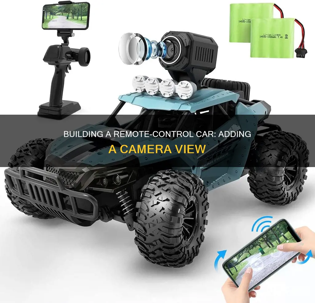
Building a remote-controlled car is a fun activity that can be done by anyone, from engineering students to hobbyists. While it is possible to build one from scratch, using a kit is a more straightforward option. This involves assembling the wheel axles, shocks system, servos, battery, electric motors, and body of the car. For those who want to build a remote-controlled car from scratch, it is important to start with a sturdy yet lightweight base, such as a Lexan plastic sheet, and then add the necessary components like wheels, steering, motors, receiver, speed controller, and battery. The process requires some basic knowledge of electronics and soldering techniques, but the final product is a unique toy car that can be controlled and customised.
| Characteristics | Values |
|---|---|
| Materials | Cardboard, wooden stick, tape, toothpick, Rx & Tx Circuit board, connecting wires, plastic gears, ball bearings, ice cream stick, hot glue gun, stationary knife, high rpm DC motor, geared DC motor, TP4056 module, Li-ion battery, switch |
| Power Supplies | 12V supply, 9V battery, 0.1uF and 470uF capacitors, 1K resistor for status LED, IC 7805 |
| Transmitter | DPDT switches, HT12E encoder, RF transmitter module, power supply circuit |
| Receiver | HT12D decoder, L293D motor driver, RF receiver module, two LEDs |
| Motors | 6V Bo motor, 12V DC motor, 12V 300RPM motor |
| Extras | Chassis, SN754410 motor driver IC, HT12E encoder IC, HT12F decoder IC, RF Rx-Tx module, 12V, 9V, and 5V battery packs, screws, screwdrivers, soldering iron, shock oil, springs, servos, battery, electric motors, body of car |
What You'll Learn
![]()
Choosing the right motor
Brushed vs. Brushless Motors
The most common type of motor used in remote-control cars is the brushed motor. Brushed motors are reliable and durable, making them an excellent choice for children and beginners. They are typically found in entry-level vehicles, which can reach speeds of up to 25 mph. Brushed motors are less powerful compared to brushless motors.
On the other hand, brushless motors are more powerful and can accelerate the car to higher speeds. If you're looking for a high-performance remote-control car, a brushless motor is the way to go. These motors are ideal for racing and can be found in mid-range and high-range models, capable of reaching speeds of up to 60 mph.
Battery Type
The type of battery you choose will also impact the performance of your remote-control car. Ni-MH (Nickel-metal Hydride) batteries are widely available and affordable, but they offer less power compared to Li-Ion (Lithium-ion) batteries. Li-Ion batteries can deliver more power to the motor, allowing your car to reach higher speeds. Consider the voltage and capacity of the battery to ensure it can provide the necessary current for optimal motor performance.
Scale and Purpose
The scale of the remote-control car is another factor to consider when choosing a motor. Different car sizes serve different purposes. For example, a smaller car in the 1/16 or 1/18 scale is ideal for indoor use or as a basher, drifter, or crawler. On the other hand, larger cars in the 1/6 scale and above can be quite expensive and require ample space to operate. Determine the intended use of your remote-control car, whether it's for racing, off-roading, or casual driving, to choose the appropriate scale and motor combination.
Aftermarket Support
When selecting a motor, it's essential to consider the availability of replacement parts and aftermarket upgrades. Opt for motors and vehicles that have readily available parts, especially if you plan on using your remote-control car for racing or high-performance applications. This will ensure that you can easily repair or upgrade your car as needed.
Budget
Your budget will also play a role in choosing the right motor. Brushed motors and Ni-MH batteries tend to be more affordable, making them suitable for entry-level and budget-conscious builders. In contrast, brushless motors and Li-Ion batteries are typically more expensive but offer higher performance. Consider your budget and the features you prioritize to make an informed decision.
Adjusting Brightness on Your Computer Camera: A Simple Guide
You may want to see also
![]()
Making the transmitter
The transmitter is the most important part of the remote control car with a camera. It is the device that sends the signal to the receiver, which then controls the car. The transmitter needs to be small, lightweight, and easy to hold. It also needs to have a clear line of sight to the receiver in order to work properly.
The first step in making the transmitter is to gather all the necessary materials. These include:
- A small, lightweight box or enclosure to house the transmitter
- A radio frequency (RF) module, which will send the signal to the receiver
- A power source, such as a battery
- A switch to turn the transmitter on and off
- A joystick or buttons to control the car's movement
- Wires and soldering equipment to connect all the components
Once you have all the materials, you can begin assembling the transmitter. Start by soldering the RF module to the power source and switch. Then, solder the joystick or buttons to the RF module. Finally, connect the power source to the transmitter's enclosure and secure all the components in place.
The next step is to test the transmitter. Turn it on and move the joystick or buttons to see if the RF module is sending a signal. You can use a multimeter to check the voltage and current of the power source, and you can also use a receiver to see if the signal is being received.
If the transmitter is working properly, you can move on to the next step, which is to mount it on the remote control car. Drill holes in the car's body to fit the transmitter and secure it in place with screws or glue.
Now, you can test the remote control car by turning on the transmitter and moving the joystick or buttons. The car should respond to your commands and move in the desired direction.
Tips for making a better transmitter
- Use a high-quality RF module that has a long range and is interference-resistant. This will ensure that the signal is strong and clear, even in areas with a lot of wireless activity.
- Consider using a rechargeable battery as the power source. This will save you money in the long run and reduce the environmental impact of your project.
- Add an LED indicator to the transmitter to show when it is on and working properly. This will help you troubleshoot any issues that may arise.
- Use heat shrink tubing or electrical tape to insulate all the soldered connections. This will prevent short circuits and ensure the safety of your project.
Covering Your Laptop Camera: Necessary Security or Paranoia?
You may want to see also
![]()
Making the receiver circuit
Components and Connections:
- The receiver circuit consists of three integrated circuits (ICs): the HT12D decoder, the L293D motor driver, and the RF receiver module.
- Wire the circuit according to the receiver schematic provided. The RF receiver module will be connected to the HT12D decoder, which decodes the data sent by the transmitter.
- The receiver circuit needs to be powered by a 12V supply. Use a 7805 regulator IC to regulate the 12V supply down to 5V.
- You can also include an LED with a 1K resistor to indicate the status of the power supply.
- Additionally, use 0.1uF and 470uF capacitors in the circuit.
Construction and Testing:
- When constructing the circuit, use red wires for positive connections and black wires for negative connections. This colour-coding will make it easier to debug the circuit if any issues arise.
- After assembling the receiver circuit, test it by providing power to the receiver. One of the LEDs on the receiver board should light up, indicating that the power supply is functioning correctly.
- Next, provide power to the transmitter circuit. The other LED near the HT12D decoder should light up, indicating a valid transmission (VT). If this LED does not light up, check your connections or replace the RF TX-RX module.
By following these steps and carefully assembling and testing the receiver circuit, you will have successfully created the core component that allows your remote-control car to receive signals and respond accordingly.
Surveillance Cameras in Hotel Rooms: What You Need to Know
You may want to see also
![]()
Mounting the motors
Motor mounting is a crucial step in building a remote-control car, and there are several factors to consider when approaching this stage of the project. Firstly, it is important to understand the original configuration of the car and its internal components. This can be achieved by disassembling the frame and examining how the parts work together.
Once you have a clear understanding of the car's existing setup, you can decide which components can be repurposed, improved, or removed. This is also an opportunity to identify areas where new features can be introduced to enhance the car's functionality.
In the context of mounting the motors, it is essential to select the right type of motor for your specific project. The size and load capacity of your remote-control car will determine whether you need a smaller 6V motor or a larger 12V DC motor. Additionally, consider the Revolutions Per Minute (RPM) rating of the motor, as higher RPM motors may be more challenging to control.
When mounting the motors, it is crucial to ensure that they are securely attached to the car's chassis. This can be achieved using appropriate fasteners or adhesives, depending on the specific design of your car. The motors should be positioned in a way that allows for efficient power transfer to the car's wheels, enabling smooth and controlled movement.
Furthermore, consider the direction and speed control of the motors. You may need to adjust the mounting position to accommodate steering mechanisms and variable speed control. In some cases, you might need to remove or modify certain parts, such as plastic sections on the wheels, to achieve the desired range of motion and turning angles.
Additionally, think about how the motors can be used for braking. By reducing the motor speed or bringing it down to zero, you can slow down and stop the vehicle. This adds a layer of control and safety to your remote-control car.
Lastly, don't forget to test the motors after mounting them to ensure they are functioning correctly and responding as expected to your control inputs. Fine-tune any adjustments as needed to optimize the performance of your remote-control car.
Easy Steps to Format Your Surveillance Camera Footage
You may want to see also
![]()
Power supply circuitry
The power supply circuitry is a crucial component of your remote-controlled car, providing the necessary power to the various systems. Here's a detailed guide on how to set up the power supply circuitry for your project:
Components and Tools:
- IC 7805: This integrated circuit (IC) is a voltage regulator that drops the input voltage from 12V to 5V. It requires a heat sink to dissipate the heat generated during voltage regulation.
- Capacitors: Use 0.1uF and 470uF capacitors in the circuit to stabilize voltage and reduce electrical noise.
- Resistors: A 1K resistor is used for the status LED, which indicates the state of the power supply.
- LED: The light-emitting diode (LED) is connected via a 1K resistor and lights up to show that the power supply is active.
- Power Sources: You will need separate power supplies for the RF transmitter and receiver circuits. The receiver circuit requires a 12V supply, while the transmitter circuit uses a 9V battery.
- Wires and Connectors: Ensure you have appropriate wires and connectors to establish the necessary electrical connections.
Circuit Diagram:
Refer to the provided circuit diagram for the power supply. This diagram illustrates the connections between the IC 7805, capacitors, resistor, LED, and power sources. Follow this diagram to wire up the supply circuit accurately.
Assembly Instructions:
- Start by connecting the 12V power supply to the circuit. This will serve as the input voltage for the IC 7805.
- Place the IC 7805 in the circuit, ensuring it has a heat sink attached. The heat sink is crucial for dissipating the heat generated during voltage regulation.
- Connect the capacitors (0.1uF and 470uF) as shown in the circuit diagram. They help stabilize the voltage and reduce electrical noise.
- Add the 1K resistor for the status LED. This resistor limits the current flowing to the LED, ensuring it operates within its safe parameters.
- Connect the LED to the circuit via the 1K resistor. The LED will illuminate when the power supply is active, providing a visual indication of the power supply's status.
- Finally, connect the 9V battery for the transmitter circuit. This battery will power the RF transmitter module.
Testing and Troubleshooting:
Before proceeding further with your remote-controlled car project, test the power supply circuitry to ensure it functions correctly:
- Use a multimeter to verify the voltage levels at various points in the circuit. Check that the input voltage is 12V and that the output voltage after the IC 7805 is regulated to 5V.
- Observe the status LED. It should illuminate when the power supply is active, indicating a functional power supply circuit.
- If there are any issues, carefully check your component connections and soldering joints for any faults. Ensure there are no short circuits or loose connections.
- If the LED does not light up, check the LED and resistor for any defects. Replace them if necessary.
- Always use a multimeter to test for continuity and voltage levels before activating the circuit to avoid potential damage to sensitive components.
BJ's Surveillance Cameras: What You Need to Know
You may want to see also
Frequently asked questions
The first step is to decide whether you want to build your RC car from scratch or use a kit. Building from scratch gives you more freedom to customize, but it is more complex and time-consuming. Using a kit is a simpler process and can still allow for some customization.
The materials needed depend on your design, but some common components include a chassis, motors, a battery, a servo, a receiver, a transmitter, and wheels. If building from scratch, you will also need materials like plastic sheets or pipes for the chassis and glue or screws for assembly.
The direction of the RC car is controlled by the servos and the motors. The servos transmit the signal for the direction, and the motors drive the wheels to turn and move the car forward or backward.
You will need a battery to power the car and its components. Common battery voltages for RC cars are 9V or 12V. Additionally, you will need a speed controller to manage the power output and a receiver to receive signals from the transmitter (remote control).