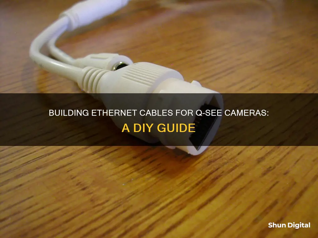
If you want to build an ethernet cable for your Q-See camera, you'll first need to decide whether you want to use a pre-made cable or make your own from bulk cable. Pre-made cables are convenient and easy to install, but bulk cable is more cost-effective and allows for a more professional-looking, tailored result.
If you're making your own cable, you'll need to follow a specific colour coding of twisted pairs to ensure high-speed, digital signalling. This standard is called 568B and should be used on both ends of the ethernet cable. You'll also need to be careful not to severely bend or pull the cable, as this could cause connectivity issues or disconnections.
Once you've run, cut, and ordered the wires according to the 568B standard, you'll need to put an RJ45 connector on, making sure the copper pairs are strongly touching the copper end of the connector. Finally, you'll use an RJ45 crimping tool to secure the connector to the cable.
What You'll Learn

Colour code the wires
Colour-coding the wires is essential when building an ethernet cable for your Q-See camera. The correct colour code ensures your cable is capable of high-speed, digital signalling and adheres to the 568B standard. This standard must be used on both ends of the ethernet cable for your IP camera to work.
The 568B standard involves ordering the wires in a specific way. The wires are colour-coded in pairs, and you must separate and straighten these pairs before ordering them. The colours of the wire pairs are:
- Orange and white
- Orange
- Green and white
- Blue
- Blue and white
- Green
- Brown and white
- Brown
Once ordered, cut the wires to the correct length. They should be short enough to fit into the RJ45 connector but leave enough sheath to reach the bottom of the cable.
After cutting the wires to size, you can put the RJ45 connector on. Ensure the copper pairs are securely connected to the copper end of the RJ45 connector. Then, use the RJ45 crimping tool to press down until you hear a "click" or "snap".
Insignia Smart TV Camera Location Guide
You may want to see also

Cut the wire
To build an ethernet cable for a Q-See camera, you will need to cut the wire at the desired location, preferably near the camera and the NVR. It is important to leave some extra wire to account for future adjustments and mistakes during the crimping process.
When cutting the wire, use wire cutters or scissors to make a clean cut. Be cautious not to damage the internal wires. After cutting, you can proceed to the next steps of stripping the outer jacket, separating the wire pairs, ordering them according to the T568B standard, and crimping the connector.
- Measure the required length of the ethernet cable, considering any future adjustments.
- Use wire cutters or scissors to cut the cable at the desired location.
- Leave some extra length on both ends to accommodate crimping errors and future maintenance.
- Ensure that you don't cut too close to the twisted pairs inside the cable.
Super Bowl Secrets: TV Cameras and More
You may want to see also

Score the sheath
To build an ethernet cable for a Q-See camera, you will need to score the sheath. Here is a detailed, step-by-step guide on how to do this:
Before you begin, ensure you have the necessary tools and materials. You will need a sharp utility knife or a cable scoring tool, and a pair of gloves to protect your hands.
Now, locate the area on the cable where you need to score the sheath. This is typically near the end of the cable, where you will be making your connections. Take your utility knife or cable scoring tool in hand and carefully make a shallow cut along the circumference of the cable's sheath. Be extremely careful not to cut too deeply and avoid cutting into the twisted pairs of wires inside the sheath. A good technique is to angle the blade away from the wires as you cut, this will help prevent any accidental cuts.
The depth of your cut should be just enough to pierce the surface of the sheath and no more. A good way to ensure you don't cut too deeply is to make multiple light passes with your knife or tool, gradually deepening the cut until you reach the desired depth. If you are using a cable scoring tool, it may have a depth guide that you can set to ensure a consistent depth with each cut.
Once you have made a full circumferential cut, you can carefully peel back the sheath to expose the twisted wire pairs. Again, be very careful not to damage the wires as you do this. If you are having trouble, you can use the tip of your knife or a small flat-head screwdriver to gently pry the sheath away from the wires.
With the sheath scored and peeled back, you can now move on to the next step of preparing the wires and making your connections. Remember to handle the exposed wires with care to avoid any damage that could compromise the performance of your ethernet cable.
Closed-Circuit TV Cameras: How Do They Work?
You may want to see also

Straighten and separate the pairs
To straighten and separate the pairs of wires in an ethernet cable, you must first cut the cable at the desired location, being careful not to cut into the wires themselves. Next, score the sheath without cutting into the twisted pairs. Then, separate the pairs and order them according to the 568B standard, which ensures high-speed digital signalling and data connection. Cut the wires to a length that is short enough to fit into the RJ45 connector but still long enough that the sheath is near the bottom of the cable.
Now, it's time to straighten the wires. Get the wires in the correct order, then gently bend them back and forth between your thumb and forefinger, alternating directions with each pull. Start closest to the sheath and work your way down to the tips of the wires. You can also try pinching each individual wire between your thumb and a screwdriver and pulling the screwdriver up the wire to straighten it. Another method is to wrap pliers in a thin cloth, clamp the wire, and then pull.
Once the wires are straight, push them into the RJ45 connector, ensuring they are all the way in and flush with the plastic at the end of the connector. Then, crimp the connector using a crimping tool.
The Evolution of Broadcast TV Cameras: Why So Large?
You may want to see also

Order into the 568B standard
The 568B standard is a colour code used for wiring eight-position RJ45 modular plugs. It is one of two wiring standards, the other being 568A. The only difference between the two is the order in which the wires connect to the RJ45 jack. In the 568B standard, the orange wire connects to pin three and the green wire connects to pin six. All other wires connect to the same pins in both standards.
The 568B standard matches the older AT&T 258A colour code and is the most widely used wiring scheme. It is approved by the ANSI/TIA/EIA standard.
The 568A and 568B standards are identical in performance. However, the 568A standard is the preferred wiring pattern as it provides backward compatibility to both one-pair and two-pair USOC wiring schemes. The 568B standard, on the other hand, provides only single-pair backward compatibility to the USOC wiring scheme.
It is important to maintain consistency when wiring a new network or expanding an existing one. Mixing the two standards can cause confusion and make troubleshooting more difficult.
Monitoring Employees: Do Managers Watch the Camerad?
You may want to see also
Frequently asked questions
You can use a standard Ethernet network cable, which transmits video data over an internet connection and can also power certain camera types. Alternatively, you can use a coaxial siamese cable, which transmits unprocessed video signals and is usually used for analog security cameras.
Ethernet connections are fast, reliable, and widely available. They are also thin, versatile, and cheaper than siamese cables. Additionally, they are easy to set up, especially with IP cameras, as they only require plugging into the cameras and recorder.
If your NVR/DVR system doesn't have a built-in network function, you can provide a network connection by connecting it to a router using an Ethernet cable.
The standard color coding is 568B, which should be used on both ends of the Ethernet cable to ensure high-speed, digital signaling. Without this standard, IP cameras will not work.


